6.2 Describe the purpose and usage of IP addresses, routes, subnet mask/prefix, and gateways
IPv4 addresses
- Internet Protocol (IP)
- uniquely identify devices at L3
- uses 32-bit addresses = 4 billion addresses supported
- IP = connectionless protocol, data loss not handled
- IP address made up of 4 octets, each one 8 bits

- consists of 2 parts:
Network IDandHost ID - 5 classes
- A, B, C for public use
- D for multicast
- E reserved for research
- IANA manages assignment and allocation of IP addresses to ISPs
- ISPs give IP addresses to their customers
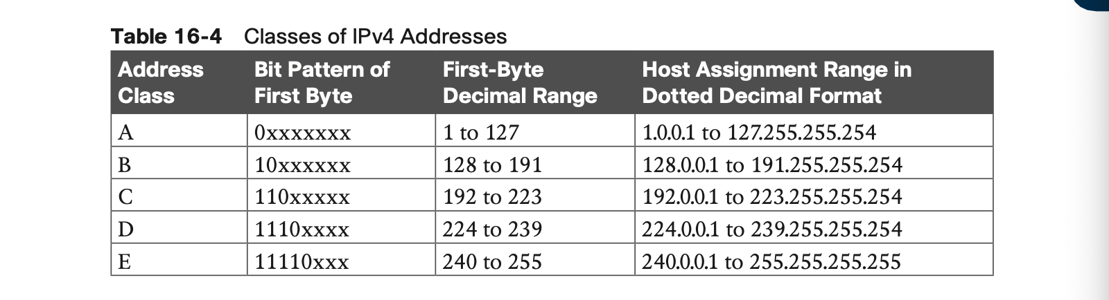
- Class A uses first byte for network and other 3 for host
- Class B uses first 2 bytes for network and last 2 for host
- Class C uses first 3 for network, last for host
IP Address mask
- used to identify which portion of the IP address is the network and which is host
Class A:255.0.0.0 or /8 = first 8 for networkClass B: 255.255.0.0 or /16 = first 16 for networkClass C: 255.255.255.0 or /24 = first 24 for network
There are 2 reserved IP addresses for each network
- network identifier: the first IP in the network such as
192.168.0.0 - broadcast address: last ip in the network such as
192.168.255.255

- Private addresses aren't routable on the internet — need NAT to translate to public IPs
Why subnetting exists
- Class A default mask = 16M+ hosts, Class B = 65,534 hosts → way too many devices on one network in practice
- Subnetting = borrowing bits from the host portion and turning them into network ID bits
CIDR / VLSM
Class-based (pre-CIDR) system:
- The mask was implied by which class the address belonged to — you didn't even get to choose it
- Class A → always /8
- Class B → always /16
- Class C → always /24
- Only 3 possible mask values existed, and which one you got depended entirely on the first bits of the IP address
CIDR (classless):
- The mask is explicitly specified alongside the address, independent of class
- Can be any value from /1 to /32 — not just /8, /16, /24
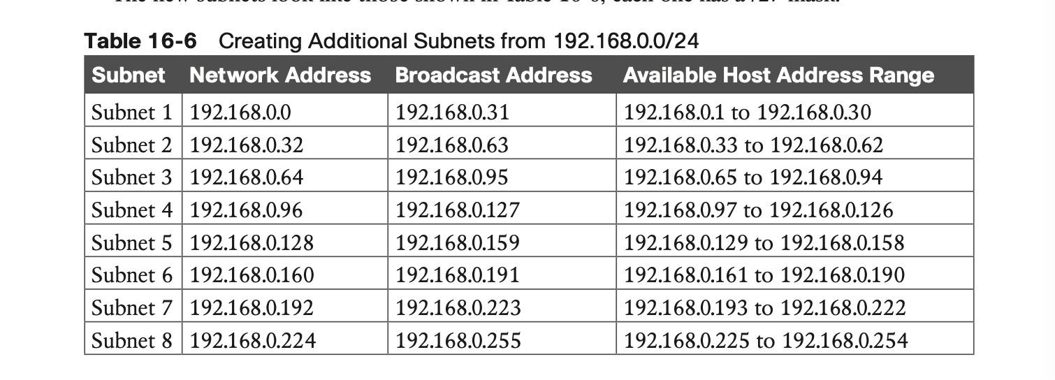
- This is what lets you do things like turn a Class C address (192.168.0.0) into a /27 instead of being stuck at /24
VLSM = the technique of actually using that freedom — specifically, using different mask lengths for different subnetscarved out of the same original network.
The key word is variable. VLSM's whole point is that not every subnet needs to be the same size.
Concrete example (imagine extending Acme):
- Say Acme's 8 departments aren't equal size — Engineering has 50 people, but the point-to-point link between two routers only needs 2 addresses
- With CIDR alone (but not VLSM), you might subnet everything uniformly — e.g., every subnet is /27 regardless of actual need
- With VLSM, you subnet unevenly to match actual demand:
- Engineering subnet → /26 (62 hosts)
- Small departments → /27 (30 hosts) or /28 (14 hosts)
- Router-to-router link → /30 (2 hosts)
- All of these masks coexist within the same parent network, sized to fit — instead of wasting addresses by giving the 2-host link the same /27 as a 30-host department
Further subnetting
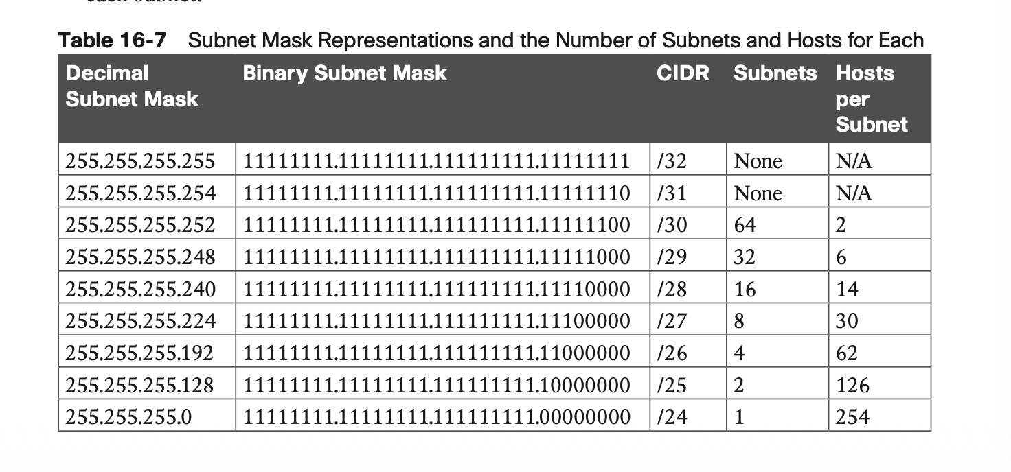
- Can keep borrowing bits: /28 → 14 hosts, /29 → 6 hosts, /30 → 2 hosts
- /30 is the classic choice for point-to-point router links (only 2 devices needed, no wasted addresses)
IPV6 addresses
Why IPv6 exists
- IPv4's 32-bit space is running out; IPv6 fixes that plus adds simpler headers and built-in security
- IPv6 = 128-bit addresses → 3.4 × 10³⁸ possible addresses (RFC 2460)
- Both IPv4/IPv6 run today; transition tech includes dual-stack (both configured on one interface — most common) and tunneling (one protocol carried inside the other)
IPv6 improvements over IPv4
- Bigger address space → better route aggregation → smaller routing tables, faster routing
- No more NAT/PAT needed — true end-to-end communication
- Autoconfiguration — devices can get an address automatically (huge for mobile/roaming)
- Multiple addresses per interface → better reliability/load balancing
- Simplified header → faster forwarding
- No broadcast (and no broadcast storms) — replaced by multicast/anycast
- IPsec built in → better security by default
Address format
- 32 hex characters, split into 8 groups of 16 bits, separated by colons:
x:x:x:x:x:x:x:x - Hex is case-insensitive
- Leading zeros in a field are optional
- One run of consecutive all-zero fields can be shortened to
::(only once per address) - Example:
2031:0000:120F:0000:0000:09C0:9A73:242C→2031:0:120F::9C0:9A73:242C
IPv6 address hierarchy/subnetting (Figure 16-9)
- IANA → assigns /23 blocks to regional registries (e.g., ARIN, APNIC)
- Registries → assign /32 blocks to ISPs
- ISPs → assign /48 subnets to customers
- Customers → subnet further, typically down to /64 (gives up to 65,536 subnets)
- Interface ID (last 64 bits) is usually derived from the device's MAC address via EUI-64 (splits the 48-bit MAC in half, inserts
0xFFFEin the middle)
5 types of IPv6 addresses
| Type | Prefix | Purpose |
|---|---|---|
| Global | 2000::/3 | Public, routable (like public IPv4) |
| Link-local | FE80::/10 | Local-segment only, not routed; used for neighbor/router discovery |
| Multicast | FF00::/8 | One-to-many delivery, replaces broadcast (e.g., FF02::1 = all-nodes, FF02::2 = all-routers) |
| Loopback | ::1 | Local testing, same purpose as IPv4's 127.0.0.1 |
| Unspecified | :: (all zeros) | Placeholder when device has no address yet (e.g., during DHCPv6) |
Routing
What routers do
- Router's main jobs: path determination (look up routing table) + forwarding the packet out the right interface
- Routers work at Layer 3, connecting different networks (vs. switches at Layer 2 connecting devices within one network)
- A router typically has 2+ interfaces, each configured with an IP on a different Layer 3 network — and usually acts as the default gateway for those local networks
How path determination works
- Router checks destination IP → looks for best match in its routing table
- Match found → forward toward that network (directly connected, or via next-hop router)
- No match → send to the default route
- No default route → drop the packet
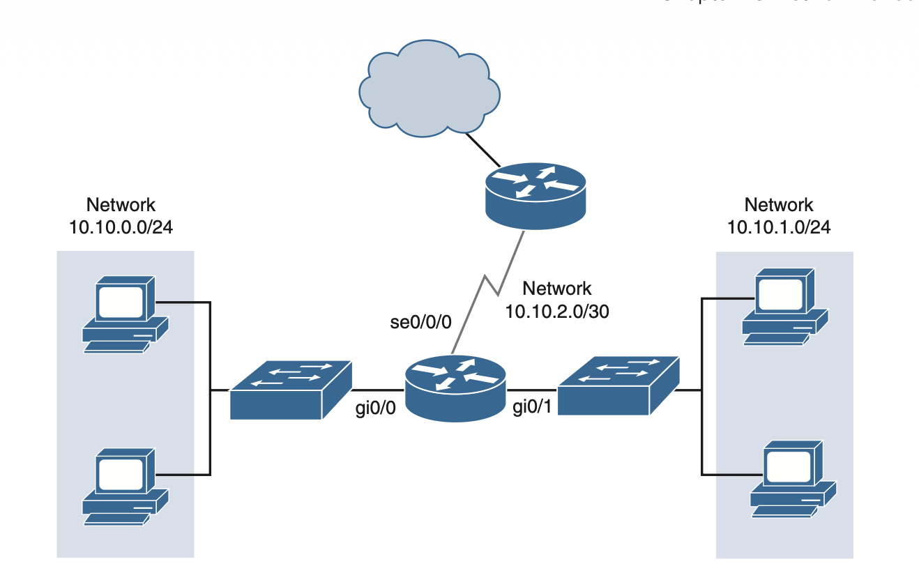
Routing table structure (Table 16-8 / Figure 16-10 example)
- Each entry = destination network → interface or next-hop
- Directly connected networks = router has an interface physically in that network
- Default route =
0.0.0.0/0— catch-all "last resort" entry, used when no explicit route matches - Default routes keep routing tables small and lookups fast (most routers don't need a full internet-scale table)
4 ways routing tables get populated
| Source | Notes |
|---|---|
| Directly connected | Router has an interface on that network |
| Static routes | Manually configured — fine for small/stable networks, doesn't scale |
| Dynamic routes | Learned automatically via routing protocols (OSPF, EIGRP, RIP, BGP, IS-IS) |
| Default routes | Catch-all fallback |
Administrative Distance (AD) — decides which route wins if multiple sources offer a route to the same network
- Lower AD = more trusted = more likely to be used
- Connected routes: AD 0 (most trusted)
- Static routes: AD 1
- Routing protocols vary — e.g., BGP = 20, RIP = 120 (higher = less trusted)
- Defaults, but admin can tweak them
Supernetting
- Opposite of subnetting: combines multiple smaller subnets into one larger routing table entry
- Keeps routing tables (especially on the internet backbone) manageable — an ISP only needs one entry for a customer's whole prefix, not every internal subnet
Longest prefix match
- When multiple routing table entries could match a destination, the router picks the most specific (longest) prefix
- Example: table has
10.10.10.0/24and10.10.0.0/16- Packet to
10.10.10.15→ matches/24(more specific) → wins - Packet to
10.10.20.15→ only matches/16→ used instead
- Packet to